Sunday, December 20, 2009

I-PD controller and tuning

A design method of multirate I-PD controller based on multirate generalized predictive control law

This paper proposes a new design method of an I-PD controller. The I-PD controller is designed in a multirate system with fast control input and slow output sampling. In order to design PID parameters of the multirate I-PD controller, the multirate I-PD controller is designed based on a multirate generalized predictive control law. Since in the multirate system a control input is updated faster than a single-rate system with slow control input and slow output sampling, the control effect of the proposed multirate I-PD controller is greater than that of a conventional single-rate one. Finally in order to show effectiveness of the proposed method, simulation results are illustrated.

http://cat.inist.fr/?aModele=afficheN&cpsidt=17893327

An Adaptive Controller based on system Identification for plants with
uncertainties using well known Tuning formulas

Abstract

Adaptive control which adequately adjusts controller
gains according to the changes in plants, has become
attractive in recent years .The controller proposed in this
paper is tuned automatically with various tuning formulas
based on the results of frequency domain system
identification for the plant. The controller first estimates
the frequency response of the plant using FFT. The
controller gains are automatically tuned so as to minimize
the error between the open loop frequency response of
the reference model and that of the actual system at a few
frequency points. For the three example processes,
reference models are derived. The frequency responses
of the reference models and that of the actual processes
are obtained. The controller gains are determined by
applying the least squares algorithm .The responses of
the plants are verified in time domain and frequency
domain after tuning the I-PD controller.

Block diagram of an I-PD controller along with process
plant


http://www.icgst.com/acse/Volume6/Issue3/P1110626005.pdf


PI-D and I-PD Control with Dynamic Prefilters
In this lab you will be controlling the one degree of freedom systems you previously modeled using PI-D and I-PD controllers with and without dynamic prefilters.
the I-PD controller we have


http://www.rose-hulman.edu/Class/ee/throne/ECE-320%20Fall%202009/lab7a.pdf

DESIGN OF ROBUST POLE ASSIGNMENT BASED ON
PARETO-OPTIMAL SOLUTIONS

ABSTRACT

In this paper, a new design method for robust pole assignment based on
Pareto-optimal solutions for an uncertain plant is proposed. The proposed design
method is defined as a two-objective optimization problem in which optimization
of the settling time and damping ratio is translated into a pole assignment
problem. The uncertainties of the plant are represented as a polytope
of polynomials, and the design cost is reduced by using the edge theorem.
The genetic algorithm is applied to optimize this problem because of its
multiple search property. In order to demonstrate the effectiveness of the
proposed design method, we applied the proposed design method to a magnetic
levitation system.


I-PD control system


http://www.ajc.org.tw/pages/PAPER/5.2PD/PI-01-22.pdf

Study on the I-PD Position Controller Design for Linear Pulse Motor DrivesABSTRACT
In this paper, a brief discussion on I-PD position controller design for linear pulse motor drive is presented. The proposed method mainly focuses on the robusteness property of the controller, which is very important for this type of system in which the variation of external load affects plant parameters. It is considered in this paper that two types of controller design methods namely; Coefficient Diagram Method (CDM), and arbitrary Pole Assignment Method (PAM) are treated and compared them. It is shown in this paper that for the case of CDM, a stability index values are chosen such that the robust property of the controller is adequately sufficient for light and heavy load operation without excessively exciting the motor. For these stability index values and an equivalent time constant, which determines the speed of responese of the system, the closed loop pole locations are automatically fixed. For the case of PAM, the closed loop pole assignments must be iteratively tried to arrive at an acceptable response.

http://nels.nii.ac.jp/els/110000031056.pdf?id=ART0000357399&type=pdf&lang=en&host=cinii&order_no=&ppv_type=0&lang_sw=&no=1260926777&cp=

PID EBook

Thursday, December 17, 2009

Video Lecture Industrial Automation and Control - Hydraulic Control and Industrial Hydraulic Circuit

Video Lecture Hydraulic Control Systems - I


Video Lecture Hydraulic Control Systems - II


Video Lecture Industrial Hydraulic Circuit


Hydraulic Control EBook

Tuesday, December 15, 2009

Video Lecture Industrial Automation and Control - CNC ,Contour generation , Motion Control and Flow Control Valves

Video Lecture Introduction To CNC Machines


Video Lecture Contour generation and Motion Control


Video Lecture Flow Control Valves

Thursday, December 10, 2009

Video Lecture Industrial Automation and Control - PLC and Sequence Control, RLL, Structured Design

Lecture Video Introduction to Sequence Control, PLC , RLL


Lecture Video Sequence Control. Scan Cycle,Simple RLL Programs


Lecture Video Sequence Control More RLL Elements RLL Syntax


Lecture Video A Structured Design Approach to Sequence


Lecture Video PLC Hardware Environment


Saturday, December 5, 2009

Video Lecture Industrial Automation and Control - Feedforward Control Ratio Control and Time Delay Systems and Inverse Response Systems

Lecture Video Feedforward Control Ratio Control


Lecture Video Time Delay Systems and Inverse Response Systems


Lecture Video Special Control Structures


Lecture Video Concluding Lesson on Process Control

Wednesday, December 2, 2009

Video Lecture Industrial Automation and Control - Introduction to Automatic Control ,PID Control and PID Control Tuning

Video Lecture Introduction to Automatic Control


Video Lecture P I D Control


Video Lecture PID Control Tuning


PID EBook

Saturday, November 28, 2009

Video Lecture Industrial Automation and Control - Signal Conditioning and Data Acquisition Systems

Lecture Series on Industrial Automation and Control by Prof. S. Mukhopadhyay, Department of Electrical Engineering, IIT Kharagpur.


Video Lecture Signal Conditioning


Video Lecture Signal Conditioning (Contd.)


Video Lecture Data Acquisition Systems

Thursday, November 26, 2009

Video Lecture Industrial Automation and Control -Sensor and Measurement

Lecture Series on Industrial Automation and Control by Prof. S. Mukhopadhyay, Dept.of Electrical Engineering, IIT Kharagpur.

Measurement Systems Characteristics Lecture Video


Temperature Measurement Lecture Video


Pressure, Force and Torque Sensors Lecture Video


Motion Sensing Lecture Video


Flow Measurement Lecture Video

Monday, November 23, 2009

Video Lecture Series on Industrial Automation and Control 1

Lecture Series on Industrial Automation and Control by Prof. S. Mukhopadhyay, Dept.of Electrical Engineering, IIT Kharagpur.


Introduction Lecture Video - 1


Architecture of Industrial Automation Systems Lecture Video - 2

Sunday, November 15, 2009

AUTO-TUNING CONTROL SYSTEM

DESIGN AND EVALUATION OF AN AUTO-TUNING CONTROL SYSTEM
FOR AN ALTITUDE TEST FACILITY
Abstract

Simulated altitude testing of large aircraft engines is a
very expensive, but essential step in the development and
certification of gas turbines used by commercial airlines. A
significant contributor to the cost of this process is the
time-intensive task of manually tuning the facility control
system that regulates the simulated flight condition. Moreover,
control system tuning must be performed each time
the test conductor changes the flight condition. An adaptive
control system that automatically performs this task can
significantly reduce the costs associated with this type of
engine testing.

This paper examines the features of an auto-tuning
controller architecture that contains both disturbance feedforward
and PID feedback components in a two-input, twooutput
multivariable configuration. The paper reviews the
underlying concepts of an auto-tuning system and contrasts
its advantages/disadvantages with respect to other adaptive
control techniques. The algorithm used to automatically
tune the controller does not require a facility model. However,
a nonlinear facility model was developed and used to
substantiate a decoupled-loop design approach, to validate
the controller design concept, and to evaluate the resulting
adaptive control system design performance. This analysis
and other practical design issues that impact the auto-tuning
control system performance are addressed in the paper. The
paper also presents results that illustrate the automatic tuning
sequence and the disturbance rejection performance
exhibited by this system during large engine transients at
several key points in the flight envelope. The auto-tuning
controller described in the paper was implemented at a
Pratt & Whitney flight test facility used in the development
of large, high bypass ratio gas turbines.

Rationale for the Auto Tune Control Concept
Unlike the MRAC and STR concepts, the Auto-Tune adjustment
(adaptation) mechanism does not require any a
priori information about system dynamics to compute the
PID controller parameters. Moreover, an Auto-Tune system
only updates the controller on an operator-demand basis.
The MRAC and STR methods do not explicitly interact
with the system operator. These two characteristics of the
auto-tuning concept were the primary factors in selecting
this adaptive concept for the altitude test facility application.
This section examines the underlying features of the
Auto-Tune concept and motivates the rationale for selecting
a PID controller for this application.

The automatic tuning performed with this scheme can be
characterized as a crude, but robust method that identifies
two key parameters characterizing process dynamics. The
Auto-Tune adaptation algorithm approaches the control
design in a manner quite familiar to first-generation single
input/single output control system designers. The fundamental
idea centers on determining the gain and frequency
at which the system dynamics become conditionally stable
under pure proportional feedback control. These frequencydomain
characteristics of the system are designated as the
ultimate gain and ultimate frequency, respectively. Using
Ziegler-Nichols relationships, the PID controller parameters
can be determined from the ultimate gain and frequency
information. It is well known that PID control systems
designed with the Ziegler-Nichols method exhibit
very good disturbance rejection performance, but tend to
have significant overshoot when responding to set-point
changes (Astrom & Hagglund - 1995). Degraded set point
responses do not present a problem in the altitude test facility
application since the control problem focuses completely
on disturbance rejection performance. The chamber
pressure and plenum pressure set points remain at fixed
values throughout an engine transient test scenario.

As in most control system synthesis problems, both time
and frequency based methods exist for formulating an experiment
that produces the information required to compute
the Ziegler-Nichols gains. In most practical control applications,
a frequency-based experiment produces superior results
and was the method chosen in this application. The
central idea in the frequency-based approach relies on the
fact that most real systems produce stable limit-cycles under
relay feedback. The theoretical basis for this statement
was developed in Astrom - 1991. The method of harmonic
balance or describing function method (Gelb and VanderVelde
– 1968) provides the mathematical framework for
analyzing relay-induced limit-cycles and extracting the
ultimate gain and ultimate frequency from the experimental
data.

http://web.iac-online.com/images/Publications/35.pdf
On-line PID Controller Design via a Single Auto-tuning Neuron

Abstract:

A simple tuning strategy for PID controller design will be proposed in this paper. With the
use of single neural estimator (SNE), three control gains of PID controller are not fixed during the
control procedure, but will be adjusted on-line such that better output response can be achieved. In
this control strategy the exact model of plant will not need to be known and identified. Lastly, two
simulation results are provided to show the control performance by using the proposed adaptive PID controller.

1. Introduction
2. Preliminaries
2.1 Auto-tuning neuron
2.2 PID controller
3. Self-tuning Adaptive PID
Controller
3.1 MIT rule
3.2 Control structure and algorithm
3.2.1 A tuning algorithm for PID control gains
3.2.2 A tuning algorithm for the SNE
4. Illustrative Examples
5. Conclusions

http://www.kyu.edu.tw/93/95paper/v8/95-061.pdf

Auto-Tuning of PID Controllers via Extremum Seeking
Abstract—The proportional-integral-derivative (PID) controller
is widely used in the process industry, but to various
degrees of effectiveness because it is sometimes poorly tuned.
The goal of this work is to present a method using extremum
seeking (ES) to tune the PID parameters such that optimal
performance is achieved. ES is a non-model based method
which searches on-line for the parameters which minimize a
cost function; in this case the cost function is representative
of the controllers performance. Furthermore, this method has
the advantage that it can be applied to plants in which
there is no knowledge of the model. We demonstrate the
ES tuning method on a cross section of plants typical of
those found in industrial applications. The PID parameters
are tuned based on the results of step response simulations to
produce a response with minimal settling time and overshoot.
Additionally, we have compared these results to those found
using other tuning methods widely used in industry.

Overall ES PID tuning scheme
.


http://www.nt.ntnu.no/users/skoge/prost/proceedings/acc05/PDFs/Papers/0401_ThA17_2.pdf

Tuesday, November 3, 2009

Auto-Tuning Control Base on Ziegler-Nichols

Auto-Tuning Control Using Ziegler-Nichols
Automatic step tests
One of the earliest auto-tuning controllers still on the market is the 53MC5000 Process Control Station from MicroMod Automation. It uses the Easy-Tune algorithm originally developed at Fischer & Porter (now part of ABB) in the early 1980s. It automatically executes a step test similar to the open-loop Ziegler-Nichols method that forces the controller to make an abrupt change in its control effort while sensor feedback is disabled.

The amount by which the process variable subsequently changes and the time required
for it to reach 63.2% of its final value indicate the steady-state gain and time constant of the process, respectively. If the sensor in the loop happens to be located some distance from the actuator, the process’s response to such a step input may also demonstrate a deadtime between the instant that the step was applied and the instant that the process variable first began to react.

These three model parameters tell the Easy- Tune algorithm everything it needs to know about the behavior of a typical process, allowing it to predict how the process will react to any corrective effort, not just step inputs. That in
turn allows the Easy-Tune algorithm to compute tuning parameters to make the controller compatible with the process.


Closed loop tests
In 1984, Karl Åström and Tore Hägglund of the Lund (Sweden) Institute of Technology
published an improved version of Ziegler and Nichols’ closed-loop tuning method. Like the open-loop method, this technique excites the process to identify its behavior, but without disabling sensor feedback.

The Åström-Hägglund method works by forcing the process variable into a series of
sustained oscillations known as a limit cycle. The controller first applies a step input to the process and holds it at a user-defined value until the process variable passes the setpoint. It then applies a negative step and waits for the process variable to drop back below the setpoint. Repeating this procedure each time the process variable passes the setpoint in either direction forces the process variable to oscillate out of sync with the control effort, but at the same frequency. See the “Relay Test” graphic. The time required to complete a single oscillation is known as the process’s ultimate period (Tu), and the relative amplitude of the two oscillations multiplied by 4/Ï€ gives the ultimate gain (Pu). Ziegler and Nichols theorized that these two parameters could be used instead of the steady-state gain, time constant, and deadtime to compute suitable tuning parameters according to their famous tuning equations or tuning rules shown in the equation on the left.

They discovered empirically that these rules generally yield a controller that responds quickly to intentional changes in the setpoint as well as to random disturbances to the process variable. However, a controller thus tuned will also tend to cause overshoot and oscillations in the process variable, so most auto-tuning controllers offer several sets of alternative tuning rules that make the controller less aggressive to varying degrees. An operator typically only has to select the required speed of response (slow, medium, fast), and the controller chooses appropriate rules automatically.

http://www.das.ufsc.br/~aarc/ensino/posgraduacao/DAS6613/Auto-Tuning%20Control%20Using%20Ziegler-Nichols.pdf
REVISITING THE ZIEGLER-NICHOLS TUNING RULES
FOR PI CONTROL — PART II
THE FREQUENCY RESPONSE METHOD
ABSTRACT

This paper presents an analysis of the Ziegler-Nichols frequency response
method for tuning PI controllers, showing that this method has severe
limitations. The limitations can be overcome by a simple modification for
processes where the time delay is not too short. By a major modification it is
possible to obtain new tuning rules that also cover processes that are lag
dominated.


I. INTRODUCTION
II. TEST BATCH AND DESIGN METHOD
2.1 The MIGO design method
2.2 The test batch
2.3 The AMIGOs tuning rules
2.4 Parameterization
III. A FIRST ATTEMPT
3.1 Stable processes
3.2 Integrating processes
3.3 Tuning rules for balanced and
delay-dominated processes
3.4 Summary
IV. ANALYSIS
4.1 Modified tuning procedures
V. THE AMIGOF TUNING RULES
5.1 Other values of Ms
5.2 How to find the frequency ωφ?
5.3 Summary
VI. AN INTERPRETATION OF
THE RESULTS
VII. EXAMPLES
Example 1. LAG DOMINATED DYNAMICS
Example 2. BALANCED LAG AND DELAY
Example 3. DELAY DOMINATED DYNAMICS
VIII. CONCLUSION


http://www.ajc.org.tw/pages/PAPER/6.4PD/AC0604-P469-FR0371.pdf

Saturday, October 24, 2009

Cascade Control Systems Design - Tunings

Procedure for Cascade Control Systems Design:
Choice of Suitable
PID TuningsAbstract: This paper provides an approach for the application of PID controllers
within a cascade control system configuration. Based on considerations about the
expected operating modes of both controllers, the tuning of both inner and outer loop
controllers are selected accordingly. This fact motivates the use of a tuning that,
for the secondary controller, provides a balanced set-point / load-disturbance performance.
A new approach is also provided for the assimilation of the inner closed-loop
transfer function to a suitable form for tuning of the outer controller. Due to the fact
that this inevitably introduces unmodelled dynamics into the design of the primary
controller, a robust tuning is needed.

2 Cascade Control


3 g-tuning for balanced Servo/Regulation
4 Approach for Cascade Control Design
4.1 Inner loop and outer loop process models
4.2 Inner loop controller tuning
Set-point tuning settings
Load-disturbance tuning settings
4.3 Model for Outer loop tuning
4.4 Outer loop controller tuning
5 Equivalent model approximation
6 Example
7 Conclusions
http://www.journal.univagora.ro/download/pdf/134.pdf

How to Tune Cascade Loops
1 An overview of Cascade Control.
What's The Inner Loop For?
• Reduces phase lag of inner process
• Disturbances to the inner loop are
compensated for before they upset the
outer loop
• Prevents non-linearities in the inner loop
from reaching the outer loop

2 Tuning Cascade Control Loops.
What happens when cascade loops
are poorly tuned?
• Loops “fight” each other
• Create oscillations
• Neither variable is properly controlled
• Operator puts loop in manual.
Tuning Cascade Loops
1. Always check for measurement and
valve-related issues.
2. Inner Loop Tuning - put slave into
Local Auto or Manual and tune the
slave controller as a normal PID loop.
3. Outer Loop Tuning - put slave into
Cascade and tune master controller
as a normal PID loop.
4. Adjust outer loop tuning values to
ensure that the RRT (Relative
Response Time) of outer loop is 3-5
times slower than the inner loop.

3 Case Study.

http://www.expertune.com/articles/UG2007/CascadeTuning.pdf

Cascade Control
Handle Processes that Challenge Regular PID Control


In previous columns we have named lags in a process as major obstacles to good temperature control. When they are inconveniently long and come in multiple stages, first try to determine where changes to process design can avoid or reduce lags. Then do your best with PID control and if you fail to obtain the response you hoped for you can turn to cascade control.


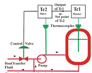
Tuning.Tune the slave loop first. Set TC1 to manual. Remove integral and derivative action from TC2 and tune it aiming for tight control. Absence of derivative avoids excessive activity of the slave loop. Overall integral action to remove offset in the vessel temperature is already provided by the master controller.


When tuning the master loop, return to cascade control, remove derivative action and tune in the normal way. Note that the slave loop now becomes part of the master loop that you are tuning at TC1. Bumpless transfer between auto, manual and cascade will be a standard feature of TC1.
Set point limits on the slave loop. If you know the range of TC2 (fluid) temperatures needed to hold the vessel temperature under all expected conditions, put those values as limits on the set point of TC2.

http://www.pacontrol.com/download/Cascade%20Control%20-%20Handle%20Processes%20that%20Challenge%20Regular%20PID%20Control.pdf


Cascade Controller - Auto Tuning

Relay Auto Tuning Of Parallel Cascade Controller
Abstract
The present work is concerned with relay auto tuning of
parallel cascade controllers. The method proposed by
Srinivasan and Chidambaram [10] to analyze the conventional
on-off relay oscillations for a single loop feedback controller is
extended to the relay tuning of parallel cascade controllers.
Using the ultimate gain and ultimate cross over frequency of
the two loops, the inner loop (PI) and outer loop (PID)
controllers are designed by Ziegler-Nichols tuning method. The
performances of the controllers are compared with the results
based on conventional relay analysis. The improved method of
analyzing biased auto tune method proposed for single
feedback controller by Srinivasan and Chidambaram [11] is
also applied to relay auto tune of parallel cascade controllers.
The proposed methods give an improved performance over that
of the conventional on-off relay tune method.

http://www.iaeng.org/publication/WCECS2007/WCECS2007_pp158-162.pdf

Tuesday, October 13, 2009

PID Controllers Auto Tuning - Relay Feedback

Relay Feedback Auto Tuning of PID Controllers

IntroductionFor a certain class of process plants, the so-called \auto tuning" procedure
for the automatic tuning of PID controllers can be used. Such a procedure
is based on the idea of using an on/off controller (called a relay controller)
whose dynamic behaviour resembles to that shown in Figure 1(a). Starting
from its nominal bias value (denoted as 0 in the Figure) the control action
is increased by an amount denoted by h and later on decreased until a value
denoted by -h.


The closed-loop response of the plant, subject to the above described ac-
tions of the relay controller, will be similar to that depicted in Figure 1(b).
Initially, the plant oscillates without a de¯nite pattern around the nominal
output value (denoted as 0 in the Figure) until a de¯nite and repeated out-
put response can be easily identi¯ed. When we reach this closed-loop plant
response pattern the oscillation period (Pu) and the amplitude (A) of the
plant response can be measured and used for PID controller tuning. In fact,
the ultimate gain can be computed as:
Having determined the ultimate gain Kcu and the oscillation period Pu
the PID controller tuning parameters can be obtained from the following
table:
Example of Relay Feedback Auto Tuning of PID Controllers

http://200.13.98.241/~antonio/cursos/control/notas/siso/atv.pdf
Relay-based PID Tuning
ABSTRACT

Relay-based auto tuning is a simple way to tune PID controllers
that avoids trial and error, and minimises the possibility
of operating the plant close to the stability limit.


http://homepages.ihug.co.nz/~deblight/AUTResearch/papers/relay_autot.pdf


An Improved Relay Auto Tuning of PID Controllers for SOPTD
Systems


Difficulties of loop tuning
When you discuss loop tuning with instrument and control
engineers, conversation soon turns to the Zeigler-Nichols
(ZN) ultimate oscillation method. Invariably the plant engineer
soon responds with ‘Oh yes, I remember the ZN tuning
scheme, we tried that and the plant oscillated itself into
oblivion — bad strategy. Moreover when it did work, the
responses are overly oscillatory’
So given the tedious and possibly dangerous plant trials
that result in poorly damped responses, it behoves one to
speculate why it is often the only tuning scheme many instrument
engineers are familiar with, or indeed ask if it has
any concrete redeeming features at all.
In fact the ZN tuning scheme, where the controller gain
is experimentally determined to just bring the plant to the
brink of instability is a form of model identification. All
tuning schemes contain a model identification component,
but the more popular ones just streamline and disguise that
part better. The entire tedious procedure of trial and error
is simply to establish the value of the gain that introduces
half a cycle delay when operating under feedback. This is
known as the ultimate gain Ku and is related to the point
where the Nyquist curve of the plant in Fig. 1(b) first cuts
the real axis.

The problem is of course, is that we rarely have the luxury
of the Nyquist curve on the factory floor, hence the
experimentation required.
Abstract Using a single symmetric relay
feedback test, a method is proposed to identify
all the three parameters of a stable second order
plus time delay (SOPTD) model with equal time
constants. The conventional analysis of relay
auto-tune method gives 27% error in the
calculation of ku,. In the present work, a method
is proposed to explain the error in the ku
calculation by incorporating the higher order
harmonics. Three simulation examples are given.
The estimated model parameters are compared
with that of Li et al. [4] method and that of
Thyagarajan and Yu [8] method. The open loop
performance of the identified model is compared
with that of the actual system. The proposed
method gives performances close to that of the
actual system. Simulation results are also given
for a nonlinear bioreactor system. The open loop
performance of the model identified by the
proposed method gives a performance close to
that of the actual system and that of the locally
linearized model. SOPTD model, symmetric relay, auto-tuning


http://ntur.lib.ntu.edu.tw/bitstream/246246/87370/1/09.pdf

DEVELOPMENT OF AN AUTO-TUNING PID AND
APPLICATIONS TO THE PULP AND PAPER INDUSTRY
Abstract
An auto-tuning industrial PID is presented. The autotuning
is realized in three steps. The process is first
adequately excited in order to generate good quality data
for the second step, the process identification. The last step
is the PID tuning based on the evaluated parametric model.
The auto-tuning PID has been implemented on two
different control systems and successful applications to
processes of the pulp and paper industry are analyzed.


http://www.iaeng.org/publication/WCECS2007/WCECS2007_pp175-181.pdf

Auto-tune system using single-run relay feedback test
and model-based controller design
Abstract

In this paper, a systematic approach for auto-tune of PI/PID
controller is proposed. A single run of the relay feedback experiment
is carried out to characterize the dynamics including the type
of damping behavior, the ultimate gain, and ultimate frequency.
Then, according to the estimated damping behavior, the process
is classified into two groups. For each group of processes,
modelbased rules for controller tuning are derived in terms of
ultimate gains and ultimate frequencies. To classify the processes,
the estimation of an apparent deadtime is required. Two artificial
neural networks (ANNs) that characterize this apparent deadtime using
the ATV data are thus included to facilitate this estimation of
this apparent deadtime. The model-based design for this auto-tuning
makes uses of parametric models of FOPDT (i.e. first-order-plus-dead-time)
and of SOPDT (i.e. second-order-plus-dead-time)
dynamics. The results from simulations show that the controllers
thus tuned have satisfactory results compared with those from
other methods.

Tuning strategy for the model-based auto-tune system.


http://w3.gel.ulaval.ca/~desbiens/publications/DevelopmentOfAnAutoTuningPID.pdf

MODIFICATION AND APPLICATION OF AUTOTUNING
PID CONTROLLER

Abstract. This contribution presents a modified autotuning algorithm of the PID controller.
The motivation for the modification of the basic autotuning algorithm is to enlarge the class
of processes to which it can be applied. The basic autotuning algorithm introduced by
Åstrom and Hägglund is extended by the preliminary identification procedure and through
the usage of the dead time compensating controller. These modifications are detailed
through the description of the algorithms’ functioning. The proposed algorithm has been
implemented in the programmable logic controller (PLC) Siemens SIMATIC S7-300. The
experimental results confirm the good robustness properties of the proposed algorithm,
which were demonstrated in a simulation study.

Structure of the modified autotuning PID controller.


http://act.rasip.fer.hr/old/papers/MED00_062.PDF

Saturday, August 22, 2009

Dynamic Analyze of Snake Robot

A Dynamic Single Actuator Vertical Climbing Robot
Abstract—A climbing robot mechanism is introduced, whichuses dynamic movements to climb between two parallel verticalwalls. This robot relies on its own internal dynamic motionsto gain height, unlike previous mechanisms which are quasistatic.One benefit of dynamics is that it allows climbingwith only a single actuated degree of freedom. We showwith analysis, simulations and experiments that this dynamicrobot is capable of climbing vertically between parallel walls.We introduce simplifications that enable us to obtain closedform approximations of the robot motion. Furthermore, thisprovides us with some design considerations and insights intothe mechanism’s ability to climb.

http://www.cs.cmu.edu/~biorobotics/papers/IROS07_Degani_0490.pdf

3-D Snake Robot Motion: Nonsmooth Modeling,Simulations, and Experiments
Abstract—A nonsmooth (hybrid) 3-D mathematical model ofa snake robot (without wheels) is developed and experimentallyvalidated in this paper. The model is based on the framework ofnonsmooth dynamics and convex analysis that allows us to easilyand systematically incorporate unilateral contact forces (i.e., betweenthe snake robot and the ground surface) and friction forcesbased on Coulomb’s law of dry friction. Conventional numericalsolvers cannot be employed directly due to set-valued force lawsand possible instantaneous velocity changes. Therefore, we showhow to implement the model for numerical treatment with a numericalintegrator called the time-stepping method. This methodhelps to avoid explicit changes between equations during simulationeven though the system is hybrid. Simulation results for theserpentine motion pattern lateral undulation and sidewinding arepresented. In addition, experiments are performed with the snakerobot “Aiko” for locomotion by lateral undulation and sidewinding,both with isotropic friction. For these cases, back-to-back comparisonsbetween numerical results and experimental results are given.


http://www.zfm.ethz.ch/~leine/papers/Transeth%20&%20Leine%20&%20Glocker%20&%20Pettersen%20-%203-D%20Snake%20Robot%20motion%20nonsmooth%20modeling%20simulations%20and%20experiments.pdf


Dynamic Analyze of Snake Robot
Abstract—Crawling movement as a motive mode seen in natureof some animals such as snakes possesses a specific syntactic anddynamic analysis. Serpentine robot designed by inspiration fromnature and snake’s crawling motion, is regarded as a crawling robot.In this paper, a serpentine robot with spiral motion model will beanalyzed. The purpose of this analysis is to calculate the vertical andtangential forces along snake’s body and to determine the parametersaffecting on these forces. Two types of serpentine robots have beendesigned in order to examine the achieved relations explained below.


http://www.waset.org/journals/waset/v29/v29-56.pdf
http://water.engr.psu.edu/reed/Education/CE%20563%20Projects/Mehta%20snakebot_nsga2%20%20Sp%2007.pdf

Optimal Gait Analysis of Snake Robot Dynamics
ABSTRACT
Though there have been a lot of research in the area ofsnake-robot kinematics and dynamics, a little attention hasbeen given to ¯nd out an optimal gait for the robot. Thisoptimal gait until now is being calculated using a graphicalmethod. An attempt, here, is made to get these optimumgait parameters using evolutionary algorithms.We intend to optimize the input power consumed by therobot for a given propulsive speed. A popular multi-objectiveevolutionary algorithm developed by Deb et al., NSGA-II isused in this work and the results are presented.Results from an approximation of objective function throughpolynomials and from the actual simulation are presented.Two di®erent frictional models are considered and their re-sults are given. The results are in good agreement with theliterature. A parametric study is also included to ¯nd min-imum population size and number of generations. The per-formance metrics are used to justify the parametrization.


AmphiBot I: an amphibious snake-like robot
Abstract
This article presents a project that aims at constructing a biologically inspired amphibious snake-like robot. The robot isdesigned to be capable of anguilliform swimming like sea-snakes and lampreys in water and lateral undulatory locomotionlike a snake on ground. Both the structure and the controller of the robot are inspired by elongate vertebrates. In particular, thelocomotion of the robot is controlled by a central pattern generator (a system of coupled oscillators) that produces travellingwavesof oscillations as limit cycle behavior. We present the design considerations behind the robot and its controller. Experimentsare carried out to identify the types of travelling waves that optimize speed during lateral undulatory locomotion on ground. Inparticular, the optimal frequency, amplitude and wavelength are thus identified when the robot is crawling on a particular surface.


http://birg2.epfl.ch/publications/fulltext/crespi05.pdf


Analysis and Design of A Multi-Link Mobile Robot (Serpentine)
Abstract
This paper is a study on dynamic behavior of a :snakerobot, called Serpentine robot, 2”* version (SR#2). TheSR#2 is the latest version of snake robots developed atFIBO as a research platform for studying serpmtinegaits. The gait is in form of sinusoidal curve, consi,deredone of the most effectiveness crawling pattem i:n thenatural world. The Active Cord Mechanism (ACM)assumption, initiated by Hirose, is implemented. Therobot motion results from different joint torquer, andfrictional reacting forces in each wheel. In this stud:y, weproposed a modified serpeniod function with steeringcommand to control the robot’s direction. We alsoperformed dynamic analysis using Kane’s method.Holonomic constraints under frictional forces andnonholonomic constraints unders velocities wereconsidered. We verified our algorithm .for directionalcontrol on this Serpentine robot both simulation andexperiment.


http://gicl.cs.drexel.edu/wiki-data/images/f/fc/AnalysisAndDesignOfAMulti-LinkMobileRobot(Serpentine).pdf

Sunday, July 5, 2009

Robotic Manipulator Dynamic article

Reliability-Based Design Optimization of Robotic System Dynamic PerformanceAbstract
In this investigation a robotic system’s dynamic performance isoptimized for high reliability under uncertainty. The dynamic capabilityequations (DCE) allow designers to predict the dynamicperformance of a robotic system for a particular configurationand reference point on the end-effector (i.e.,point design). Herethe DCE are used in conjunction with a reliability-based designoptimization (RBDO) strategy in order to obtain designs withrobust dynamic performance with respect to the end-effector referencepoint. In this work a unilevel performance measure approach(PMA) is used to perform RBDO. This is important forthe reliable design of robotic systems in which a solution to theDCE is required for each constraint call. The method is illustratedon a robot design problem.


Velocity Effects on Robotic Manipulator Dynamic Performance
Abstract
Background. This article explores the effect that velocities haveon a nonredundant robotic manipulator’s ability to accelerate itsend-effector, as well as to apply forces/moments to the environmentat the end-effector. This work considers velocity forces, includingCoriolis forces, and the reduction of actuator torque withrotor velocity described by the speed-torque curve, at a particularconfiguration of a manipulator. The focus here is on nonredundantmanipulators with as many actuators as degrees-of-freedom.Method of Approach. Analysis of the velocity forces is accomplishedusing optimization techniques, where the optimizationproblem consists of an objective function and constraints whichare all purely quadratic forms, yielding a nonconvex problem.Dialytic elimination is used to find the globally optimal solutionto this problem. The proposed method does not use iterative numericaloptimization methods.


more pdf


Dynamic Performance as a Criterion for Redundant Manipulator Control
Abstract
Kinematically redundant manipulators havebeen proven to offer certain advantages over more heavilyconstrained systems. One such advantage is the extra degreesof-freedom can be used for other tasks such as maintaininga posture which affords higher acceleration capability in thedirection of the desired motion. However certain issues arisewhen considering the control of these mechanisms due tothe lack of invertability of the rectangular Jacobian matrix.Here this issue is addressed by augmenting the rectangularJacobian with a characterization of the null space motions.This approach allows for a gradient-based control scheme,based upon the Dynamic Capability Equations, to increase ormaintain the local performance capability of a manipulator asit performs some task. Simulation results of the application ofthis control scheme to a six degree-of-freedom (DOF) planarmanipulator are given to illustrate the control’s advantageson a highly redundant system.

more pdf

The Actuation Effciency, a Measure of Acceleration Capability for Non-Redundant Robotic Manipulators
Abstract
This article presents a performance measure, the ActuationEffciency, which describes the imbalance betweenthe end-effector accelerations achievable in differentdirections of non-redundant robotic manipulators.A key feature of the proposed measure is thatin its development the differences in units betweentranslational and rotational accelerations are treatedin a physically meaningful manner. The measure alsoindicates oversized actuators, since this contributes tothe imbalance in achievable accelerations. The developmentof this measure is based on the formulation ofthe Dynamic Capability Equations. The shape of theDynamic Capability Hypersurface, which is desined bythe Dynamic Capability Equations, is a weak indicatorof the level of imbalance in achievable end-effectoraccelerations.


The Dynamic Capability Equations: A New Tool for Analyzing Robotic Manipulator PerformanceAbstract
The Dynamic Capability Equations (DCE) provide anew description of robot acceleration and force capabilities. Theserefer to a manipulator’s ability to accelerate its end-effector,and to apply forces to the environment at the end-effector. Thekey features in the development of these equations are that theycombine the analysis of end-effector accelerations, velocities andforces while addressing the difference in units between translationaland rotational quantities. The equations describe themagnitudes of translational and rotational acceleration and forceguaranteed to be achievable in every direction, from a particularconfiguration, given the limitations on the manipulator’s motortorques. They also describe the effect of velocities on thesecapabilities contributed by the Coriolis and centrifugal forces, aswell as the reduction of actuator torque capacity due to motorspeed. This article focuses on non-redundant manipulators withas many actuators as degrees-of-freedom.


more pdf


Non-Redundant Robotic Manipulator Acceleration Capability andthe Actuation Efficiency Measure
Abstract
This article presents a performance measure, the actuationeficiency, which describes the imbalance betweenthe end-effector accelerations achievable in differentdirections of non-redundant robotic manipulators.A key feature of the proposed measure is that inits development the unitam differences between linearand angular accelerations are treated in a physicallymeaningful manner. The memure also indicatesoversized actuators, since this contributes to the imbalancein achievable accelerations. The developmentof this measure is based on the formulation of theDynamic Capability Hypersurface. The shape of thishypersurface is a weak indicator of the level of imbalancein achievable end-effector accelerations.
more pdf

SOME PROBLEMS OF MANIPULATOR MOTION CONTROL
The purpose of manipulator control is tomaintain the dynamic response of a computer-basedmanipulator in accordance with some prespecifiedsystem performance and desired goals. In general,the dynamic performance of a manipulator directlydepends on the efficiency of the control algorithmsand the dynamic model of the manipulator. Thecontrol problem consists of obtaining dynamicmodels of the physical robot arm system and thenspecifying corresponding control laws or strategiesto achieve the desired system response andperformance.

Monday, June 15, 2009

What is a PID controller and Tuning

What is a PID controller?


A PID (Proportional Integral Derivative) controller is a common instrument used in industrial control applications. A PID controller can be used for regulation of speed, temperature, flow, pressure and other process variables. Field mounted PID controllers can be placed close to the sensor or the control regulation device and be monitored centrally using a SCADA system.
Example: Temperature Control using a Digital PID controller
A typical PID temperature controller application could be to continuously vary a regulator which can alter a process temperature. This may be a pulsed switching device for electrical heaters or by opening and closing a gas valve. A heat only PID temperature controller uses a reverse output action, i.e. more power is applied when the temperature is below the setpoint and less power when above. PID control for injection and extrusion applications often employ additional cooling control outputs and usually require multiple controllers.
A PID controller (sometimes called a three term controller) reads the sensor signal, normally from a thermocouple or RTD, and converts the measurement to engineering units e.g. Degrees C. It then subtracts the measurement from a desired setpoint to determine an error.
The error is acted upon by the three (P, I & D) terms simultaneously:
PID Controller Theory
The following section examines PID controller theory and provides further explanation of the question `how do PID controllers work'.
Proportional (Gain)
The error is multiplied by a negative (for reverse action) proportional constant P, and added to the current output. P represents the band over which a controller's output is proportional to the error of the system. E.g. for a heater, a controller with a proportional band of 10 deg C and a setpoint of 100 deg C would have an output of 100% up to 90 deg C, 50% at 95 Deg C and 10% at 99 deg C. If the temperature overshoots the setpoint value, the heating power would be cut back further. Proportional only control can provide a stable process temperature but there will always be an error between the required setpoint and the actual process temperature.
Integral (Reset)
The error is integrated (averaged) over a period of time, and then multiplied by a constant I, and added to the current control output. I represents the steady state error of the system and will remove setpoint / measured value errors. For many applications Proportional + Integral control will be satisfactory with good stability and at the desired setpoint.
Derivative (Rate)
The rate of change of the error is calculated with respect to time, multiplied by another constant D, and added to the output. The derivative term is used to determine a controller's response to a change or disturbance of the process temperature (e.g. opening an oven door). The larger the derivative term, the more rapidly the controller will respond to changes in the process value.
Tuning of PID Controller Terms
The P, I and D terms need to be "tuned" to suit the dynamics of the process being controlled. Any of the terms described above can cause the process to be unstable, or very slow to control, if not correctly set. These days temperature control using digital PID controllers have automatic auto-tune functions. During the auto-tune period the PID controller controls the power to the process and measures the rate of change, overshoot and response time of the plant. This is often based on the Zeigler-Nichols method of calculating controller term values. Once the auto-tune period is completed the P, I & D values are stored and used by the PID controller.
Joe Crew is the Product Manager at
Data Track Process Instruments Ltd. Data Track manufactures digital panel meters, large number displays, PID controllers, signal conditioners and remote data acquisition systems for the process and control industry. Data Track can also supply HMI touchscreen operator panels and SCADA software. The Tracker 300 series of PID Controllers are fully configurable by PC software and feature universal input, single loop integrity, autotune PID, heat / cool control actions and condition monitoring features.
Article Source:
http://EzineArticles.com/?expert=Joe_Crew


Model-based Tuning Methods for Pid Controllers

Author: BIN

The manner in which a measured process variable responds over time to changes in the controller output signal is fundamental to the design and tuning of a PID controller. The best way to learn about the dynamic behavior of a process is to perform experiments, commonly referred to as "bump tests." Critical to success is that the process data generated by the bump test be descriptive of actual process behavior. Discussed are the qualities required for "good" dynamic data and methods for modeling the dynamic data for controller design. Parameters from the dynamic model are not only used in correlations to compute tuning values, but also provide insight into controller design parameters such as loop sample time and whether dead time presents a performance challenge. It is becoming increasingly common for dynamic studies to be performed with the controller in automatic (closed loop). For closed loop studies, the dynamic data is generated by bumping the set point. The method for using closed loop data is illustrated. Concepts in this work are illustrated using a level control simulation.

FORM OF THE CONTROLLER

The methods discussed here apply to the complete family of PID algorithms. Examples presented will explore the most popular controller of the PID family, the Proportional-Integral (PI) controller:

In this controller, u(t) is the controller output and is the controller bias. The tuning parameters are controller gain, , and reset time, . Because is in the denominator, smaller values of reset time provide a larger weight to (increase the influence of) the integral term.

CONTROLLER DESIGN PROCEDURE

Designing any controller from the family of PID algorithms entails the following steps:

specifying the design level of operation,
collecting dynamic process data as near as practical to this design level,
fitting a first order plus dead time (FOPDT) model to the process data, and
using the resulting model parameters in a correlation to obtain initial controller tuning values.
The form of the FOPDT dynamic model is:
[2]
where y(t) is the measured process variable and u(t) is the controller output signal. When Eq. 2 is fit to the test data, the all-important parameters that describe the dynamic behavior of the process result:

Steady State Process Gain,

Overall Process Time Constant,

Apparent Dead Time,

These three model parameters are important because they are used in correlations to compute initial tuning values for a variety of controllers [1]. The model parameters are also important because:

the sign of indicates the sense of the controller (+ reverse acting; – direct acting)

the size of indicates the maximum desirable loop sample time (be sure sample time )

the ratio indicates whether a Smith predictor would show benefit (useful if )

the dynamic model itself can be employed within the architecture of feed forward, Smith predictor, decoupling and other model-based controller strategies.

DEFINING GOOD PROCESS TEST DATA

As discussed above, the collection and analysis of dynamic process data are critical steps in controller design and tuning. A "good" set of data contains controller output to measured process variable data that is descriptive of the dynamic character of the process. To obtain such a data set, the answer to all of these questions about your data should be "yes" [1]. Ultimately, it is your responsibility to consider these steps to ensure success.

Was the process at steady state before data collection started?
Suppose a controller output change forces a dynamic response in a process, but the data file only shows the tail end of the response without showing the actual controller output change that caused the dynamics in the first place. Popular modeling tools will indeed fit a model to this data, but it will skew the fit in an attempt to account for an unseen "invisible force." This model will not be descriptive of your actual process and hence of little value for control. To avoid this problem, it is important that data collection begin only after the process has settled out. The modeling tool can then properly account for all process variations when fitting the model.

Did the test dynamics clearly dominate the process noise?
When generating dynamic process data, it is important that the change in controller output cause a
response in the process that clearly dominates the measurement noise. A rule of thumb is to define a
noise band of ±3 standard deviations of the random error around the process variable during steady
operation. Then, when during data collection, the change in controller output should force the process variable to move at least ten times this noise band (the signal to noise ratio should be greater than ten). If you meet or exceed this requirement, the resulting process data set will be rich in the dynamic information needed for controller design.

Were the disturbances quiet during the dynamic test?
It is essential that the test data contain process variable dynamics that have been clearly (and in the ideal world exclusively) forced by changes in the controller output as discussed in step 2. Dynamics caused by unmeasured disturbances can seriously degrade the accuracy of an analysis because the modeling tool will model those behaviors as if they were the result of changes in the controller output signal. In fact, a model fit can look perfect, yet a disturbance that occurred during data collection can cause the model fit to be nonsense. If you suspect that a disturbance event has corrupted test data, it is conservative to rerun the test.

Did the model fit appear to visually approximate the data plot?
It is important that the modeling tool display a plot that shows the model fit on top of the data. If the two lines don't look similar, then the model fit is suspect. Of course, as discussed in step 3, if the data has been corrupted by unmeasured disturbances, the model fit can look great yet the usefulness of the analysis can be compromised.

NOISE BAND AND SIGNAL TO NOISE RATIO
When generating dynamic process data, it is important that the change in the controller output signal causes a response in the measured process variable that clearly dominates the measurement noise. One way to quantify the amount of noise in the measured process variable is with a noise band. As illustrated in Fig. 1, a noise band is based on the standard deviation of the random error in the measurement signal when the controller output is constant and the process is at steady state. Here the noise band is defined as ±3 standard deviations of the measurement noise around the steady state of the measured process variable (99.7% of the signal trace is contained within the noise band). While other definitions of the noise band have been proposed, this definition is conservative when used for controller design.

When generating dynamic process data, the change in controller output should cause the measured process variable to move at least ten times the size of the noise band. Expressed concisely, the signal to noise ratio should be greater than ten. In Fig. 1, the noise band is 0.25°C. Hence, the controller output should be moved far and fast enough during a test to cause the measured exit temperature to move at least 2.5°C. This is a minimum specification. In practice it is conservative to exceed this value.


Figure 1 – Noise Band Encompasses ± 3 Standard Deviations Of The Measurement Noise

CONTROLLER TUNING FROM CORRELATIONS
The recommended tuning correlations for controllers from the PID family are the Internal Model Control (IMC) relations [1]. These are an extension of the popular lambda tuning correlations and include the added sophistication of directly accounting for dead time in the tuning computations.

The first step in using the IMC (lambda) tuning correlations is to compute, , the closed loop time constant. All time constants describe the speed or quickness of a response. The closed loop time constant describes the desired speed or quickness of a controller in responding to a set point change. Hence, a small (a short response time) implies an aggressive or quickly responding controller. The closed loop time constants are computed as:

Aggressive Tuning: (See online version for picture of formula)

Moderate Tuning: ("")

Conservative Tuning: ("")

Final tuning is verified on-line and may require tweaking. If the process is responding sluggishly to disturbances and changes in the set point, the controller gain is too small and/or the reset time is too large. Conversely, if the process is responding quickly and is oscillating to a degree that makes you uncomfortable, the controller gain is too large and/or the reset time is too small.

EXAMPLEs: In online copy

PI Controller Tuning Map


Figure 6 – How PI controller tuning parameters impact set point tracking performance

CONCLUSIONS
Understanding the dynamic behavior of a process is essential to the proper design and tuning of a PID controller. The recommended design and tuning methodology is to: step, pulse or otherwise perturb the controller output near the design level of operation, record the controller output and measured process variable data as the process responds, and fit a first order plus dead time (FOPDT) dynamic model to this process data, use the dynamic model parameters in a correlation to compute P-Only, PI, PID and PID with Filter test your controller to ensure satisfactory performance.

LITERATURE CITED

1. Cooper, Douglas, "Practical Process Control Using Control Station," Published by Control Station,Inc, Storrs, CT (2004).

For more information about model-based tuning techniques and technologies, please see our other resources below:

PID Control – Practical Process Control Training (2 Day Workshop)

http://www.bin95.com/process_control_atlanta_training.htm

Complete list of authors:
Jeffrey Arbogast – Department of Chemical Engineering
Douglas J. Cooper, PhD – Control Station, Inc.
Robert C. Rice, PhD – Control Station, Inc.
To see the full online version with pictures, please visit http://www.bin95.com/PID_Controller_Design.htm

About the Author:

More from these authors and much more. please see ”More PID TRaining resources”...

Article Source: ArticlesBase.com - Model-based Tuning Methods for Pid Controllers