Auto-Tuning Control Using Ziegler-Nichols
Automatic step testsOne of the earliest auto-tuning controllers still on the market is the 53MC5000 Process Control Station from MicroMod Automation. It uses the Easy-Tune algorithm originally developed at Fischer & Porter (now part of ABB) in the early 1980s. It automatically executes a step test similar to the open-loop Ziegler-Nichols method that forces the controller to make an abrupt change in its control effort while sensor feedback is disabled.
The amount by which the process variable subsequently changes and the time required
for it to reach 63.2% of its final value indicate the steady-state gain and time constant of the process, respectively. If the sensor in the loop happens to be located some distance from the actuator, the process’s response to such a step input may also demonstrate a deadtime between the instant that the step was applied and the instant that the process variable first began to react.
These three model parameters tell the Easy- Tune algorithm everything it needs to know about the behavior of a typical process, allowing it to predict how the process will react to any corrective effort, not just step inputs. That in
turn allows the Easy-Tune algorithm to compute tuning parameters to make the controller compatible with the process.

Closed loop tests
In 1984, Karl Åström and Tore Hägglund of the Lund (Sweden) Institute of Technology
published an improved version of Ziegler and Nichols’ closed-loop tuning method. Like the open-loop method, this technique excites the process to identify its behavior, but without disabling sensor feedback.
The Åström-Hägglund method works by forcing the process variable into a series of
sustained oscillations known as a limit cycle. The controller first applies a step input to the process and holds it at a user-defined value until the process variable passes the setpoint. It then applies a negative step and waits for the process variable to drop back below the setpoint. Repeating this procedure each time the process variable passes the setpoint in either direction forces the process variable to oscillate out of sync with the control effort, but at the same frequency. See the “Relay Test” graphic. The time required to complete a single oscillation is known as the process’s ultimate period (Tu), and the relative amplitude of the two oscillations multiplied by 4/π gives the ultimate gain (Pu). Ziegler and Nichols theorized that these two parameters could be used instead of the steady-state gain, time constant, and deadtime to compute suitable tuning parameters according to their famous tuning equations or tuning rules shown in the equation on the left.
They discovered empirically that these rules generally yield a controller that responds quickly to intentional changes in the setpoint as well as to random disturbances to the process variable. However, a controller thus tuned will also tend to cause overshoot and oscillations in the process variable, so most auto-tuning controllers offer several sets of alternative tuning rules that make the controller less aggressive to varying degrees. An operator typically only has to select the required speed of response (slow, medium, fast), and the controller chooses appropriate rules automatically.
http://www.das.ufsc.br/~aarc/ensino/posgraduacao/DAS6613/Auto-Tuning%20Control%20Using%20Ziegler-Nichols.pdf
REVISITING THE ZIEGLER-NICHOLS TUNING RULES
FOR PI CONTROL — PART II
THE FREQUENCY RESPONSE METHOD
ABSTRACT
This paper presents an analysis of the Ziegler-Nichols frequency response
method for tuning PI controllers, showing that this method has severe
limitations. The limitations can be overcome by a simple modification for
processes where the time delay is not too short. By a major modification it is
possible to obtain new tuning rules that also cover processes that are lag
dominated.
I. INTRODUCTION
II. TEST BATCH AND DESIGN METHOD
2.1 The MIGO design method
2.2 The test batch
2.3 The AMIGOs tuning rules
2.4 Parameterization
III. A FIRST ATTEMPT
3.1 Stable processes
3.2 Integrating processes
3.3 Tuning rules for balanced and
delay-dominated processes
3.4 Summary
IV. ANALYSIS
4.1 Modified tuning procedures
V. THE AMIGOF TUNING RULES
5.1 Other values of Ms
5.2 How to find the frequency ωφ?
5.3 Summary
VI. AN INTERPRETATION OF
THE RESULTS
VII. EXAMPLES
Example 1. LAG DOMINATED DYNAMICS
Example 2. BALANCED LAG AND DELAY
Example 3. DELAY DOMINATED DYNAMICS
VIII. CONCLUSION
http://www.ajc.org.tw/pages/PAPER/6.4PD/AC0604-P469-FR0371.pdf
Procedure for Cascade Control Systems Design:
Choice of Suitable PID TuningsAbstract: This paper provides an approach for the application of PID controllers
within a cascade control system configuration. Based on considerations about the
expected operating modes of both controllers, the tuning of both inner and outer loop
controllers are selected accordingly. This fact motivates the use of a tuning that,
for the secondary controller, provides a balanced set-point / load-disturbance performance.
A new approach is also provided for the assimilation of the inner closed-loop
transfer function to a suitable form for tuning of the outer controller. Due to the fact
that this inevitably introduces unmodelled dynamics into the design of the primary
controller, a robust tuning is needed.
2 Cascade Control

3 g-tuning for balanced Servo/Regulation
4 Approach for Cascade Control Design
4.1 Inner loop and outer loop process models
4.2 Inner loop controller tuning
Set-point tuning settings
Load-disturbance tuning settings
4.3 Model for Outer loop tuning
4.4 Outer loop controller tuning
5 Equivalent model approximation
6 Example
7 Conclusions
http://www.journal.univagora.ro/download/pdf/134.pdf
How to Tune Cascade Loops
1 An overview of Cascade Control.
What's The Inner Loop For?
• Reduces phase lag of inner process
• Disturbances to the inner loop are
compensated for before they upset the
outer loop
• Prevents non-linearities in the inner loop
from reaching the outer loop
2 Tuning Cascade Control Loops.
What happens when cascade loops
are poorly tuned?
• Loops “fight” each other
• Create oscillations
• Neither variable is properly controlled
• Operator puts loop in manual.
Tuning Cascade Loops
1. Always check for measurement and
valve-related issues.
2. Inner Loop Tuning - put slave into
Local Auto or Manual and tune the
slave controller as a normal PID loop.
3. Outer Loop Tuning - put slave into
Cascade and tune master controller
as a normal PID loop.
4. Adjust outer loop tuning values to
ensure that the RRT (Relative
Response Time) of outer loop is 3-5
times slower than the inner loop.
3 Case Study.
http://www.expertune.com/articles/UG2007/CascadeTuning.pdf
Cascade Control
Handle Processes that Challenge Regular PID Control
In previous columns we have named lags in a process as major obstacles to good temperature control. When they are inconveniently long and come in multiple stages, first try to determine where changes to process design can avoid or reduce lags. Then do your best with PID control and if you fail to obtain the response you hoped for you can turn to cascade control.
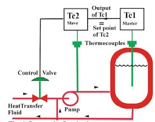
Tuning.Tune the slave loop first. Set TC1 to manual. Remove integral and derivative action from TC2 and tune it aiming for tight control. Absence of derivative avoids excessive activity of the slave loop. Overall integral action to remove offset in the vessel temperature is already provided by the master controller.
When tuning the master loop, return to cascade control, remove derivative action and tune in the normal way. Note that the slave loop now becomes part of the master loop that you are tuning at TC1. Bumpless transfer between auto, manual and cascade will be a standard feature of TC1.
Set point limits on the slave loop. If you know the range of TC2 (fluid) temperatures needed to hold the vessel temperature under all expected conditions, put those values as limits on the set point of TC2.
http://www.pacontrol.com/download/Cascade%20Control%20-%20Handle%20Processes%20that%20Challenge%20Regular%20PID%20Control.pdf
Cascade Controller - Auto Tuning
Relay Auto Tuning Of Parallel Cascade Controller
Abstract
The present work is concerned with relay auto tuning of
parallel cascade controllers. The method proposed by
Srinivasan and Chidambaram [10] to analyze the conventional
on-off relay oscillations for a single loop feedback controller is
extended to the relay tuning of parallel cascade controllers.
Using the ultimate gain and ultimate cross over frequency of
the two loops, the inner loop (PI) and outer loop (PID)
controllers are designed by Ziegler-Nichols tuning method. The
performances of the controllers are compared with the results
based on conventional relay analysis. The improved method of
analyzing biased auto tune method proposed for single
feedback controller by Srinivasan and Chidambaram [11] is
also applied to relay auto tune of parallel cascade controllers.
The proposed methods give an improved performance over that
of the conventional on-off relay tune method.
http://www.iaeng.org/publication/WCECS2007/WCECS2007_pp158-162.pdf


