In order to be able to better predict the system response, an
alternative topology is needed. One example of an easier to
tune topology is the PIV controller shown in Fig.3. This
controller basically combines a position loop with a velocity loop.
More specifically, the result of the position error multiplied
by Kp becomes a velocity correction command. The integral
term, Ki now operates directly on the velocity error instead of
the position error as in the PID case and finally, the Kd term
in the PID position loop is replaced by a Kv term in the PIV
velocity loop. Note however, they have the same units,
Nm/ (rad/sec).
PIV control requires the knowledge of the motor velocity,
labeled velocity estimator in Fig.3. This is usually formed by
a simple filter, however significant delays can result and must
be accounted for if truly accurate responses are needed.
Alternatively, the velocity can be obtained by use of a velocity
observer. This observer requires the use of other state variables
in exchange for providing zero lag filtering properties. In either
case, a clean velocity signal must be provided for PIV control.
As an example of this tuning approach, we investigate the
response of a Compumotor Gemini series servo drive and built in
controller using the same motor from the previous example.
Again, we begin with observing the response to a step input
command with no external disturbance torque (Td = 0).
Tuning the PIV Loop
To tune this system, only two control parameters are needed,
the bandwidth (BW) and the damping ratio (z). An estimate
of the motor’s total inertia, ˆ J and damping, ˆ b are also required
at set-up and are obtained using the motor/drive set up utilities.
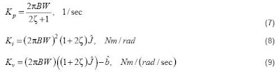
Figure 4 illustrates typical response plots for various bandwidths
and damping ratios.
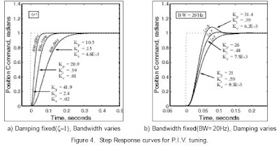
With the damping ratio fixed, the bandwidth directly relates to
the system rise time as shown in Fig.4 a). The higher the bandwidth,
the quicker the rise and settling times. Damping, on the other hand,
relates primary to overshoot and secondarily to rise time. The less
damping, the higher the overshoot and the slightly quicker the rise
time for a fixed bandwidth. This scenario is shown in Fig. 4 b).
The actual internal PIV gains can be calculated directly from
the bandwidth and damping values along with the estimates of
the inertia, ˆ J and motor viscous damping, ˆ b , making their use
straightforward and easy to implement. The actual analytical
expressions are described in equations (7) - (9).
In reality, the user never wants to put a step command into their
mechanics, unless of course the step is so small that no damage
will result. The use of a step response in determining a system’s
performance is mostly traditional. The structure of the PIV
control and for that matter, the PID control is designed to reject
unknown disturbances to the system. Fig.1 shows this unknown
torque disturbance, Td as part of the servo motor model.
Source ( pdf )
http://www.compumotor.com/whitepages/ServoFundamentals.pdf
 and approximate it (as follows) because the disturbance


