NEURAL ADAPTIVE TACKING CONTROL OF A
LOW SPEED DC SERVO SYSTEM
Hu Hongjie Chen Jingquan Er Lianjie
DC SERVO SYSTEM
The low speed system’s hardware setup is composed of a
permanent dc motor, driving circuit, servo amplifier
(PWM), a mechanical frame as an inertial load, interface
circuit (A/D and D/A), an encoder for position sensing,
and a personal computer (PETIUM I 133) is used as the
programming environment, using Borlandc31 as
programming language for the real-time control
application. Sampling time is defined as 5ms. The block
diagram of the hardware setup is shown in figure

more ( pdf )
Two Adaptive Friction Compensation for DC Servomotors
Abstract
Two advanced control strategies of adaptive friction
Compensation For DC servomotor are presented in this paper,
the first is used for The direct on-line friction compensation in
the velocity control system, The second is making use of an
adaptive inverse neural network controller In the position control
system. Both are composed of an adaptive Compensator for
the nonlinear stiction and Coulomp friction in Parallel with a
PID regulator. Experiments show that much improvement
Of performance has attained respect to conventional controller

more ( pdf )
Feedforward and IMP Control Applied to a DC Servo Motor
Feedforward and IMP Control Applied to a DC Servo Motor
1.0 Introduction
The purpose of this report is to compare feedforward and internal
model principle (IMP) control applied to a DC servo motor.
These control schemes will be tested with known sinusoidal inputs.
The performance of the control schemes will be compared to the
Open loop performance of the system. System identification of
the motor is another task that will be performed.
Feedforward Control
Feedforward control was implemented by inverting (2) to yield:

this gives an overall transfer function of one for the system as
can be seen from figure 3. Even though H(s) is not a proper
transfer function, the control system could be implemented
because the input signal is a known sine wave so the first and
second derivatives can be readily calculated.
can be seen from figure 3. Even though H(s) is not a proper
transfer function, the control system could be implemented
because the input signal is a known sine wave so the first and
second derivatives can be readily calculated.

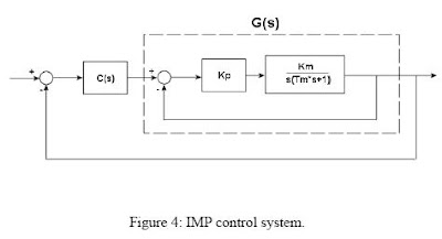
Internal Model Principle Control (IMP)
The internal model principle [Control System Design, Goodwin
et. al.] can be used to design a controller when the input to the
system is know and can be modeled in the Laplace domain.
The internal model principle [Control System Design, Goodwin
et. al.] can be used to design a controller when the input to the
system is know and can be modeled in the Laplace domain.

more ( pdf )
MODELLING AND CONTROL OF A DC SERVO MOTOR
WITH LABVIEW
MODELLING AND CONTROL OF A DC SERVO MOTOR
WITH LABVIEW
OBJECTIVES
This is a hands-on session on the application of computer-based
control to a voltage-controllable electro-mechanical system – the
DC motor. The session is mainly concerned with the modelling
and control of a DC servo motor system, fully instrumented with
position and velocity measurements. National Instrument’s
LabVIEW will be the control software for the experiment. At the
end of the experiment, you should have some experience in
• Simple static and dynamic modelling of the DC motor system,
• Manual and feedback control of the system for velocity tracking
To benefit more fully from this session, students should read the
manual and answer the pre-laboratory questions (Q1-Q3) before
going to the laboratory.

Fig1. DC Servomotor
More pdf
Real –Time DC Motor Position Control by Fuzzy Logic
and PID Controllers Using Labview
Abstract
This paper presents the position control of a DC
motor using Fuzzy Logic and PID Control algorithms. Fuzzy
Logic and PID controllers are designed based on labview
program, and the real - time position control of the DC motor
was realized by using DAQ device. The experimental results
demonstrate that the responses of DC motor with FLC show a
satisfactory, well damped control performance.

Fig .3. The block diagram of proposed PID Controller structure
More pdf
DC Servomotor Controller
This is an experiment on the closed loop DC servomotor control
system (SMC). It will able to be used for practical use with/without
some modifications. The closed loop servo mechanism requires
real-time servo operations, such as position control, velocity
control and torque control. It will be suitable for implementation
to any embedded 32 bit RISC processors as a middleware. In this
project, these operations are processed with only a cheap 8 bit
microcontroller.


